
Activities
Q1. Activity 3.2: Let us observe Take an electric cell, turn it around and look at it carefully (Fig. 3.2). Do you notice a positive (+) sign and a negative (−) sign marked on the electric cell? Do you also notice that it has a small protruding metal cap on one side and a flat metal disc on the other side? 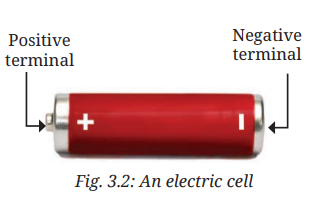 All electric cells have two terminals; one is called positive (+ve) while the other is negative (−ve). The metal cap is the positive terminal of the electric cell and the metal disc is the negative terminal. The electric cell is a portable source of electrical energy.
Answer:
Observations:
- An electric cell has two terminals.
- Positive (+) terminal: Small protruding metal cap.
- Negative (−) terminal: Flat metal disc.
- The electric cell is a portable source of electrical energy.
Q2. Activity 3.3: Let us experiment In a torch, we generally use more than one cell. Are those placed in any particular order? Take a torch which uses two cells. Open its cell compartment and take out the cells. Put the cells back in a different order. Also, try reversing the direction of one cell. Then, slide the switch and check whether the lamp glows in each case. Check the order in which the cells were placed in the torch when the lamp glows. 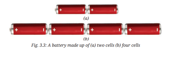 The lamp glows when the cells are placed in the order as shown in Fig. 3.3. Notice how the terminals of the two cells are connected. The positive terminal of one cell is connected to the negative terminal of the next cell. Such a combination of two or more cells is called a battery.
Answer:
Observations:
- The lamp glows only when cells are placed in the correct order.
- The positive terminal of one cell must be connected to the negative terminal of the next cell.
- This connection is called series connection.
- A combination of two or more cells connected in series is called a battery.
Q3. Activity 3.5: Let us observe Take an LED of any colour (Fig. 3.6) and observe. Do you see any filament inside it? Notice the length of two wires attached to the LED. Do you find one of those longer than the other? Unlike incandescent lamps, LEDs do not have filaments (Fig. 3.6). They also have two terminals, but one is positive (attached to a longer wire) and the other is negative (the shorter wire). A torch may use one or more LEDs, sometimes of different shapes, in its lamp. 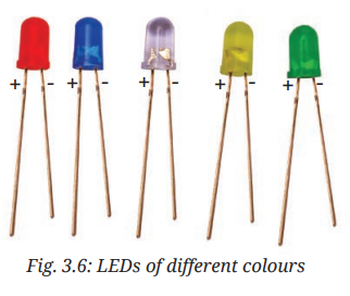
Answer:
Observations:
- LEDs do not have filaments.
- They have two terminals:
- Positive terminal — attached to the longer wire.
- Negative terminal — attached to the shorter wire.
- LEDs emit light when current flows through them in the correct direction.
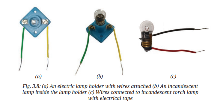
Q4. Activity 3.6: Let us construct Take an electric cell, an incandescent lamp used in a torch, a cell holder, a lamp holder, and four lengths of electric wire. Remove about 1 cm of the plastic covering from both ends of each wire to expose the metal. Attach two wires to the two ends of the cell holder as shown in Fig. 3.7a. Insert the cell in the holder such that its negative terminal is towards the spring side of the holder (Fig. 3.7b). In case a cell holder is not available, fix the two wires to the cell using electrical tape (Fig. 3.7c). 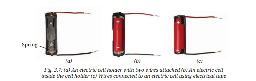 Attach two wires to the screws of the lamp holder as shown in Fig. 3.8a. Fix the lamp in the holder by turning it around in the holder (Fig. 3.8b). In case a lamp holder is not available, use electrical tape to attach two wires to the two ends of the lamp (Fig. 3.8c).
  Now, we are ready to connect the cell to the lamp to make it glow. We will conduct this activity in two parts—prediction and observation. Some of the ways in which the lamp and the cell can be connected are shown in Table 3.1.
| Table 3.1: Trying to make the lamp glow | |||
|---|---|---|---|
| S.No. | Arrangement of Cell and Lamp | Prediction | Observation |
| 1. | |||
| 2. | |||
| 3. | |||
| 4. | |||
| 5. | |||
| 6. | |||
- Predict, for each arrangement, if the lamp will glow or not and write your prediction in Table 3.1.
- Now, connect the lamp and the cell, and observe if the lamp glows or not. Note down your observation in Table 3.1. Also, for the lamps which glow, colour their glass bulbs yellow.
Answer:
Completed Table 3.1:
| S.No. | Arrangement of Cell and Lamp | Prediction | Observation |
|---|---|---|---|
| 1. | Cell and lamp connected with two wires (closed circuit) | Glows | Glows |
| 2. | Only one wire connected (open circuit) | Does not glow | Does not glow |
| 3. | Wires connected but cell reversed | Glows (incandescent lamp) | Glows (incandescent lamp) |
| 4. | Lamp connected to one terminal of cell only | Does not glow | Does not glow |
| 5. | Both wires connected to same terminal of cell | Does not glow | Does not glow |
| 6. | Cell and lamp connected with switch closed | Glows | Glows |
Conclusion:
- An incandescent lamp glows when there is a complete circuit.
- It does not matter which terminal of the cell is connected to which terminal of the lamp.
- Polarity does not matter for an incandescent lamp.
Q5. Activity 3.8: Let us construct Collect two drawing pins, a safety pin (or a paper clip), two wires, and a small piece of cardboard. Insert a drawing pin through the ring of the safety pin and fix it to the cardboard piece, ensuring that the safety pin can rotate freely (Fig. 3.11a). Fix the second drawing pin to the cardboard piece so the free end of the safety pin can touch it (Fig. 3.11b). Connect a wire to each drawing pin—our switch is ready! 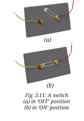
Answer:
Method to make a simple switch:
- Take a piece of cardboard as the base.
- Insert a drawing pin through the ring of a safety pin and fix it to the cardboard.
- Ensure the safety pin can rotate freely.
- Fix a second drawing pin so that the free end of the safety pin can touch it.
- Connect a wire to each drawing pin.
Working:
- OFF position: Safety pin does not touch the second drawing pin — circuit is broken.
- ON position: Safety pin touches the second drawing pin — circuit is complete.
Q6. Activity 3.9: Let us test Connect the electric cell, lamp, and switch as shown in Fig. 3.12a. Does the lamp glow? Rotate the free end of the safety pin till it touches the other drawing pin as shown in Fig. 3.12b. Does the lamp glow now? When the safety pin touches both drawing pins, it closes the gap and completes the path, and allows the current to flow. We call this the ON position (Fig. 3.12b) where the circuit is closed and current flows from the cell's positive to negative terminal making the lamp glow. When the safety pin does not touch the second drawing pin, the gap in the circuit prevents current flow, and the lamp does not glow. In this OFF position (Fig. 3.12a), we say that the circuit is open. 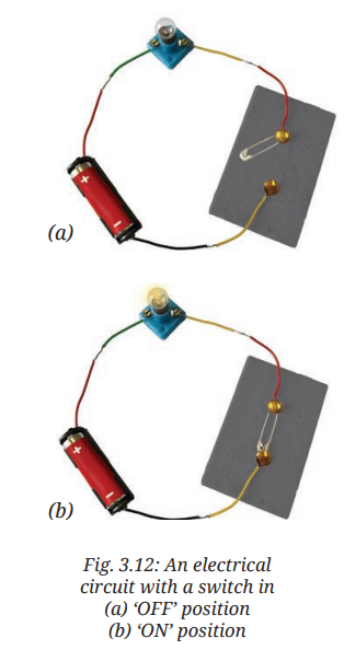 Note that a switch can be placed anywhere in a circuit. A switch is a simple device that either completes or breaks a circuit. The switches used for lights and other devices at home work the same way, though they are designed differently.
Answer:
Observations:
- OFF position: Lamp does not glow (circuit is open).
- ON position: Lamp glows (circuit is closed).
Conclusion:
- A switch is a device that completes or breaks a circuit.
- ON position: Circuit is closed — current flows.
- OFF position: Circuit is open — no current flows.
Q7. Activity 3.11: Let us identify Connect an electric cell and a lamp while leaving the two ends of wires free as shown in Fig. 3.15a. Touch the two free ends of the wires momentarily. Does the lamp glow? If yes, our tester is ready. We can use this tester to identify the materials through which electric current passes. Collect objects of different materials, such as metal spoons, coins, cork, rubber, glass, keys, pins, plastic scale, wooden block, aluminium foil, candle, sewing needle, cardboard, paper, and pencil lead. One by one, touch the free ends of the tester's wires to both ends of each object you have collected (Fig. 3.15b). Make sure the wires don't touch each other. Does the lamp glow every time? Record your observations in Table 3.3. [IMAGE NEEDED: (a) Conduction tester (b) Using the conduction tester for testing a material]
| S.No. | Object | Material it is made up of | Lamp glows (Yes/No) | Conclusion (Conductor/ Insulator) |
|---|---|---|---|---|
| 1. | Stick | Wood | No | |
| 2. | Scale | Plastic | ||
| 3. | Bangle | Glass | ||
| 4. | Paper strip | Paper | ||
| 5. | Candle | Wax | ||
| 6. | Key | Metal | ||
| 7. | Eraser | Rubber | ||
| 8. | ||||
| 9. |
Answer:
Completed Table 3.3:
| S.No. | Object | Material it is made up of | Lamp glows (Yes/No) | Conclusion (Conductor/ Insulator) |
|---|---|---|---|---|
| 1. | Stick | Wood | No | Insulator |
| 2. | Scale | Plastic | No | Insulator |
| 3. | Bangle | Glass | No | Insulator |
| 4. | Paper strip | Paper | No | Insulator |
| 5. | Candle | Wax | No | Insulator |
| 6. | Key | Metal | Yes | Conductor |
| 7. | Eraser | Rubber | No | Insulator |
| 8. | Aluminium foil | Aluminium | Yes | Conductor |
| 9. | Coin | Metal | Yes | Conductor |
| 10. | Pencil lead | Graphite | Yes | Conductor |
Conclusion:
- Conductors: Materials through which electric current can flow easily (e.g., metals, pencil lead/graphite).
- Insulators: Materials through which electric current cannot flow (e.g., wood, plastic, glass, rubber, paper, wax).
- Metals are used for making wires because they are good conductors.
- Plastic and rubber are used to cover wires because they are insulators and protect us from electric shocks.
In-text Questions
Q1. Can you help Nihal by adding some more uses to his lists? Also, suggest some other ways of grouping the uses of electricity. (From the opening scenario)
Answer:
Answer: Uses of electricity can be grouped in various ways.
Additional uses of electricity:
- Charging mobile phones and laptops
- Running electric fans and air conditioners
- Operating washing machines and dishwashers
- Powering traffic lights and signals
- Running elevators and escalators
- Operating medical equipment (ECG, X-ray machines)
- Powering electric vehicles
- Lighting streets and homes
- Running computers and servers
- Operating printers and photocopiers
Other ways of grouping uses:
- By sector: Domestic (homes), Industrial (factories), Commercial (offices/shops), Agricultural (farming), Transport, Healthcare
- By function: Lighting, Heating, Cooling, Entertainment, Communication, Transportation
Q2. Are those placed in any particular order? (From Activity 3.3)
Answer:
Answer: Yes, cells are placed in a particular order.
The positive terminal of one cell is connected to the negative terminal of the next cell. This is called series connection.
Q3. Which part of the lamp glows? (From Section 3.2.3)
Answer:
Answer: The filament (thin wire inside the glass bulb) glows.
The filament gets hot and glows to produce light when electric current passes through it.
Q4. Do you see any filament inside it? (From Activity 3.5)
Answer:
Answer: No, LEDs do not have filaments.
Unlike incandescent lamps, LEDs produce light through a semiconductor material, not through a glowing filament.
Q5. Do you find one of those longer than the other? (From Activity 3.5)
Answer:
Answer: Yes, the longer wire is the positive terminal, and the shorter wire is the negative terminal of the LED.
Q6. Does the LED glow? (From Section 3.2.5)
Answer:
Answer:
- LED glows when positive terminal (longer wire) is connected to the positive terminal of the battery, and negative terminal (shorter wire) is connected to the negative terminal of the battery.
- LED does not glow when the connections are reversed.
Q7. Does the LED glow again? (From Section 3.2.5)
Answer:
Answer: No, the LED does not glow when the connections are interchanged.
This is because current can pass through an LED in one direction only.
Q8. How will you decide which is the positive terminal of this battery? (From Section 3.2.5)
Answer:
Answer: The terminal of the holder which is connected to the positive terminal of one cell is the positive terminal of the battery.
The terminal connected to the negative terminal of the other cell is the negative terminal of the battery.
Q9. Then, how are the terminals of the cells connected? (From Section 3.2.5 — referring to side-by-side cells)
Answer:
Answer: When cells are placed side by side, a thick wire or metal strip connects the positive terminal of one cell to the negative terminal of the next cell.
To help with proper placement, + and − symbols are typically printed inside the battery compartment.
Q10. Does the lamp glow? (From Activity 3.9)
Answer:
Answer:
- OFF position: Lamp does not glow.
- ON position: Lamp glows.
Q11. Does the lamp glow now? (From Activity 3.9)
Answer:
Answer: Yes, the lamp glows now.
Reason: The safety pin touches both drawing pins, completing the circuit. Current flows from the cell through the lamp, making it glow.
Q12. Can we represent the circuits in a simpler manner? (From Section 3.3)
Answer:
Answer: Yes, we can represent circuits using standard symbols for electrical components.
A representation of an electrical circuit using symbols is called a circuit diagram.
Q13. Are your circuit diagrams similar to Fig. 3.14a and Fig. 3.14b respectively? (From Section 3.3) 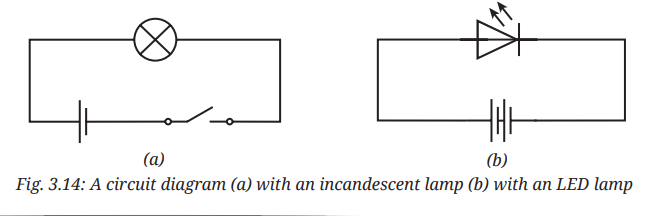
Answer:
Answer: Yes, circuit diagrams drawn using standard symbols should match the figures in the textbook.
- Fig. 3.14a: Circuit diagram with an incandescent lamp.
- Fig. 3.14b: Circuit diagram with an LED.
Q14. Why did we use metal wires for making electric circuits? Can we not use some other materials for wires? (From Section 3.4)
Answer:
Answer: We use metal wires because metals are good conductors of electricity.
We cannot use other materials (like plastic, wood, rubber) for wires because they are insulators — they do not allow electric current to flow through them.
Q15. Why are electric wires covered with plastic or rubber? (From Section 3.4)
Answer:
Answer: Electric wires are covered with plastic or rubber because these materials are insulators.
They protect us from electric shocks by preventing current from passing through when we touch the wires.
Q16. Do you think the electric current will pass through those materials in such a circuit? (From Section 3.4)
Answer:
Answer: No, electric current will not pass through materials other than metals (like wood, plastic, rubber, glass, paper).
These materials are insulators and do not allow current to flow through them.
Exercises
Q1. Choose the incorrect statement. (i) A switch is the source of electric current in a circuit. (ii) A switch helps to complete or break the circuit. (iii) A switch helps us to use electricity as per our requirement. (iv) When the switch is in 'OFF' position, there is an air gap between its terminals.
Answer:
Answer: (i) A switch is the source of electric current in a circuit.
Explanation:
- (i) Incorrect: A switch is not a source of electric current. The source of electric current is an electric cell or battery.
- (ii) Correct: A switch helps to complete (ON) or break (OFF) the circuit.
- (iii) Correct: A switch allows us to use electricity as per our requirement.
- (iv) Correct: In the OFF position, there is an air gap between the terminals of the switch.
Q2. Observe Fig. 3.16. With which material connected between the ends A and B, the lamp will not glow? [IMAGE NEEDED: A circuit diagram with ends A and B where different materials can be connected]
Answer:
Answer: The lamp will not glow when an insulator is connected between ends A and B.
Examples of insulators: Wood, plastic, rubber, glass, paper, cardboard, wax.
Explanation:
- Insulators do not allow electric current to pass through them.
- The circuit remains open (incomplete), so the lamp does not glow.
Q3. In Fig. 3.17, if the filament of one of the lamps is broken, will the other glow? Justify your answer. 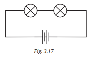
Answer:
Answer: No, the other lamp will not glow.
Justification:
- The lamps are connected in series (one after the other).
- A broken filament in one lamp breaks the circuit.
- The circuit becomes open, so current cannot flow through either lamp.
- Therefore, the other lamp will not glow.
Q4. A student forgot to remove the insulator covering from the connecting wires while making a circuit. If the lamp and the cell are working properly, will the lamp glow?
Answer:
Answer: No, the lamp will not glow.
Explanation:
- The plastic/rubber covering on wires is an insulator.
- If the ends of the wires still have the insulator covering, no electrical contact can be made.
- The circuit remains open (incomplete).
- Even though the lamp and cell are working, current cannot flow, so the lamp does not glow.
Q5. Draw a circuit diagram for a simple torch using symbols for electric components.
Answer:
Answer:
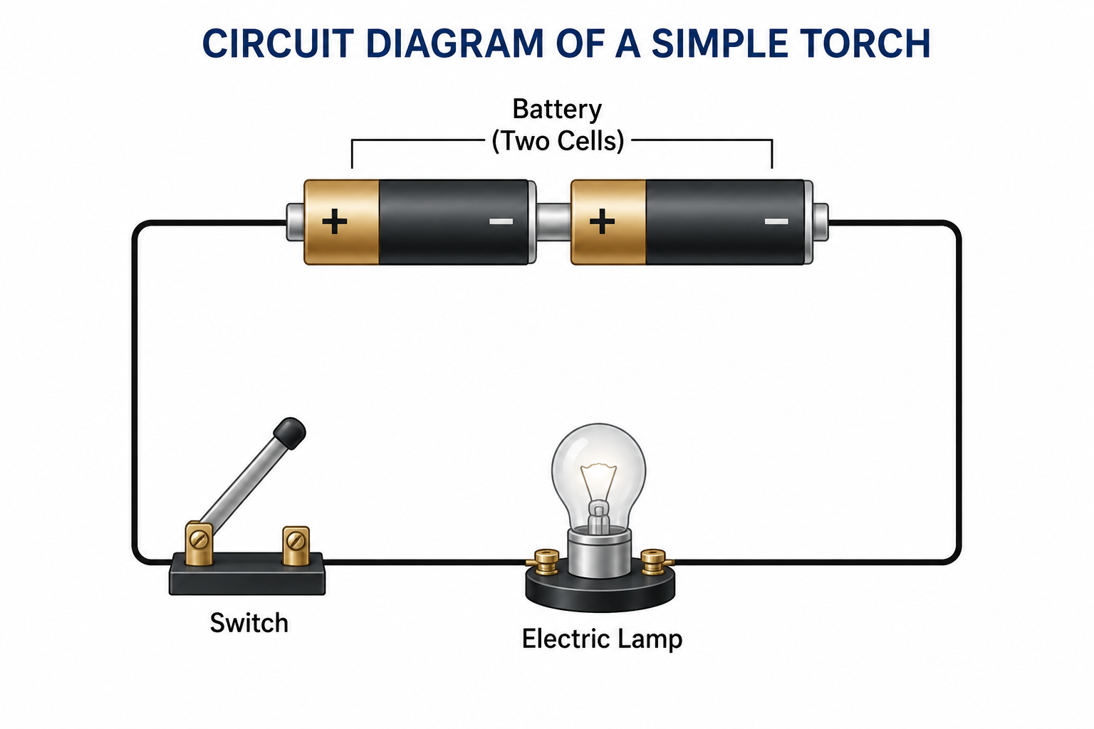
Components and their symbols:
- Battery: Two cells connected in series (+ to −). Symbol: Two cell symbols side by side.
- Switch: In ON position (closed circuit). Symbol: A gap with a line connecting.
- Electric lamp: Symbol: A circle with a cross (×) inside.
- Wires: Connecting all components in a closed loop.
Note: If using LED, use the LED symbol (triangle with arrow) instead of the lamp symbol.
Q6. In Fig. 3.18: (i) If S₂ is in ON position, S₁ is in OFF position, which lamp(s) will glow? (ii) If S₂ is in OFF position, S₁ is in ON position, which lamp(s) will glow? (iii) If S₁ and S₂ both are in ON position, which lamp(s) will glow? (iv) If both S₁ and S₂ are in OFF position, which lamp(s) will glow? [IMAGE NEEDED: A circuit diagram with two switches S₁ and S₂ and two lamps L₁ and L₂]
Answer:
Answers:
(i) S₂ ON, S₁ OFF:
- No lamp glows.
- Reason: S₁ is OFF, so the circuit is broken.
(ii) S₂ OFF, S₁ ON:
- L₁ glows (if S₁ controls L₁).
- L₂ does not glow because S₂ is OFF.
(iii) S₁ and S₂ both ON:
- Both L₁ and L₂ glow.
- Both circuits are complete.
(iv) S₁ and S₂ both OFF:
- No lamp glows.
- Both circuits are broken.
Q7. Vidyut has made the circuit as shown in Fig. 3.19. Even after closing the circuit, the lamp does not glow. What can be the possible reasons? List as many possible reasons as you can for this faulty operation. What will you do to find out why the lamp did not glow? 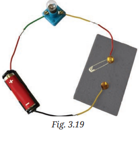
Answer:
Possible reasons why the lamp does not glow:
- Broken filament — the lamp is fused.
- Dead or weak cell — not enough voltage to make the lamp glow.
- Loose connections — wires not properly connected to terminals.
- Broken wire — one of the connecting wires may be broken inside the insulation.
- Faulty switch — even in ON position, switch may not be making contact.
- Insulator covering — ends of wires still covered with plastic/rubber.
- Short circuit — wires may be touching each other directly, bypassing the lamp.
- Wrong polarity (if using LED) — LED connected in reverse.
What to do to find out:
- Check all connections and ensure they are tight.
- Ensure the ends of wires are stripped of insulation.
- Replace the lamp with a known working lamp.
- Replace the cell with a known working cell.
- Check the switch by bypassing it with a direct wire.
- Check for any broken wires.
- If using LED, check the polarity (+ to +, − to −).
Q8. In Fig. 3.20, in which case(s) the lamp/LED will not glow when the switch is closed? 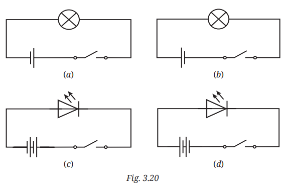
Answer:
Answer: The lamp/LED will not glow in cases where:
- The circuit is not complete (open circuit).
- The cell is dead.
- The lamp filament is broken.
- The LED is connected with wrong polarity (+ to −, − to +).
- There is a short circuit (wires touching directly).
- An insulator is part of the circuit.
- The switch is faulty (not making contact even in ON position).
Q9. Suppose the '+' and '−' symbols cannot be read on a battery. Suggest a method to identify the two terminals of this battery.
Answer:
Answer: The terminals of the battery can be identified using an LED.
Method:
- Take a working LED (longer wire = positive, shorter wire = negative).
- Connect the LED to the battery with a resistor in series (to prevent damage).
- If the LED glows, the terminal connected to the longer wire of the LED is the positive terminal of the battery.
- If the LED does not glow, reverse the connections. When it glows, the correct polarity is identified.
Alternative method: Use a voltmeter (if available) — it will show a positive reading when connected correctly.
Q10. You are given six cells marked A, B, C, D, E, and F. Some of these are working and some are not. Design an activity to identify which of them are working. (i) List the items that you require. (ii) Write the procedure that you will follow. (iii) With the items, carry out the activity to identify the cells that are working.
Answer:
Activity: Testing Cells
(i) Items required:
- Six cells marked A, B, C, D, E, F
- One working electric lamp or LED with a resistor
- Cell holder (or electrical tape)
- Two connecting wires
- One known working cell (reference cell, optional)
(ii) Procedure:
- Prepare a tester circuit using the working lamp, connecting wires, and a lamp holder.
- Connect cell A to the tester circuit.
- Observe whether the lamp glows. Record your observation.
- Repeat steps 2-3 for cells B, C, D, E, and F.
- Record all observations in a table.
(iii) Observations and conclusions:
| Cell | Lamp glows (Yes/No) | Conclusion |
|---|---|---|
| A | Working / Not working | |
| B | Working / Not working | |
| C | Working / Not working | |
| D | Working / Not working | |
| E | Working / Not working | |
| F | Working / Not working |
Q11. Using an LED that requires two cells in series to glow, Tanya made the circuit as shown in Fig. 3.21. Will the lamp glow? If not, draw the wires for correct connections. 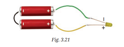
Answer:
Answer: The lamp will not glow if the connections are incorrect.
Common mistakes:
- Cells not connected in series properly (+ of one to − of the other).
- LED connected with wrong polarity (+ to −, − to +).
- Break in the circuit (loose connection).
Correct connections:
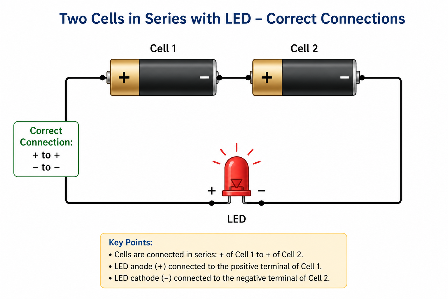
- Battery: Connect positive terminal of cell 1 to negative terminal of cell 2 (series).
- LED: Connect longer wire (positive) of LED to positive terminal of battery.
- LED: Connect shorter wire (negative) of LED to negative terminal of battery.
Exploratory Projects
Q1. Suppose that due to some problem, the power supply is disrupted in your area for two days. List out which actions from your daily life you would not be able to do.
Answer:
Project: Life Without Electricity
Aim: To understand our dependence on electricity in daily life.
Actions that would not be possible without electricity:
- Lighting: Cannot use electric lights; need candles or oil lamps.
- Charging: Cannot charge mobile phones, tablets, or laptops.
- Appliances: Cannot use fans, ACs, refrigerators, washing machines, microwaves, ovens, electric kettles, toasters, mixers.
- Entertainment: Cannot watch TV, use computers, or gaming consoles.
- Communication: Internet will not work; limited mobile usage.
- Water supply: Electric water pumps will not work.
- Food storage: Refrigerator will stop working; food may spoil.
- Cooking: Electric stoves/ovens will not work; need gas stove or other alternatives.
- Cooling/Heating: No fans, ACs, or heaters.
- Work/Study: Cannot use computers or projectors.
Reflection: This activity helps appreciate the importance of electricity and encourages energy conservation.
Q2. Using a solar panel (Fig. 3.22a) as a source of electrical energy, make a circuit to run a toy fan (Fig. 3.22b) as shown in Fig. 3.22c. 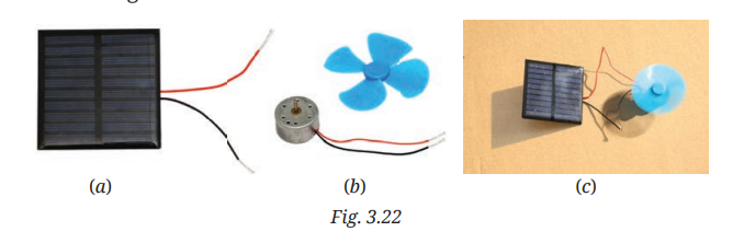
Answer:
Project: Solar-Powered Fan
Aim: To make a circuit using a solar panel to run a toy fan.
Materials required:
- Small solar panel
- Toy fan (small DC motor with fan blades)
- Connecting wires
Method:
- Place the solar panel in sunlight.
- Connect the positive terminal of the solar panel to one wire and the negative to the other.
- Connect the free ends of the wires to the toy fan.
- The fan will start rotating when the solar panel receives sunlight.
Observation:
- The fan rotates in sunlight.
- If the panel is covered, the fan stops.
Conclusion: Solar energy can be converted into electrical energy using a solar panel.
Q3. Visit an electrical items shop. With the help of the shopkeeper, identify the various types of cells available. For each cell, also find out which device(s) it is used for. Prepare a report.
Answer:
Project Report: Types of Cells and Their Uses
| S.No. | Type of Cell/Battery | Common Devices | Key Features |
|---|---|---|---|
| 1. | AA (Penlight) Cell (1.5V) | Torchlights, remote controls, clocks, toys, radios | Commonly used; alkaline, zinc-carbon, rechargeable |
| 2. | AAA (Micro) Cell (1.5V) | TV remotes, small torches, laser pointers, wireless mice | Smaller than AA cells |
| 3. | D (Mono) Cell (1.5V) | Large torchlights, radios, musical instruments | Larger size, higher current capacity |
| 4. | C (Baby) Cell (1.5V) | Toys, portable radios, flashlights | Medium size |
| 5. | 9V Battery | Smoke detectors, multimeters, walkie-talkies | Rectangular shape with snap connectors |
| 6. | Button Cells (1.5V or 3V) | Watches, hearing aids, calculators, key fobs | Flat, coin-shaped |
| 7. | Lithium Cells (3V) | Cameras, computer motherboards, key fobs | Long shelf life, high energy density |
| 8. | Rechargeable Cells (1.2V) | Cameras, cordless phones, power tools, toys | NiMH or Lithium-ion; can be recharged |
| 9. | Lead-Acid Battery | Vehicles, inverters, UPS, solar storage | Large, heavy; provides high current |
| 10. | Lithium-ion Battery | Smartphones, laptops, power banks, EVs | Rechargeable; high energy density |
Q4. Prepare a list of objects in your home under three categories: (i) Objects which are electrical insulators only (ii) Objects which are electrical conductors only (iii) Objects which are made of both, whose some parts are insulators and some electrical conductors
Answer:
Project: Identifying Conductors and Insulators at Home
(i) Objects which are electrical insulators only:
- Plastic rulers
- Rubber erasers
- Wooden furniture
- Glass bottles
- Paper and cardboard
- Candle wax
- Cotton cloth
- Ceramic mugs/plates
- Plastic toys
- Rubber bands
(ii) Objects which are electrical conductors only:
- Metal coins
- Keys (metal)
- Aluminium foil
- Metal spoons/forks
- Iron nails
- Copper wire
- Steel utensils
- Pencil lead (graphite)
- Metal jewellery
(iii) Objects made of both (some parts conductors, some insulators):
| Object | Conductor Part | Insulator Part |
|---|---|---|
| Electric iron | Metal plate, heating element | Plastic/wooden handle, plastic body |
| Electric kettle | Metal heating element | Plastic handle, outer plastic body |
| Fan | Metal motor, metal blades | Plastic body, plastic switches |
| Electrical plug/switch | Metal pins/contacts | Plastic casing |
| Mobile charger | Copper wires inside | Plastic/rubber outer covering |
| Toaster | Metal heating elements | Plastic outer body, plastic knob |
Science and Society
Q1. Electric cells or batteries are compact portable sources of electrical energy that make the use of some electrical devices more convenient. These cells and batteries come in various shapes and sizes for different purposes, such as cylindrical batteries for torchlights, clocks, remotes, toys; button cells for watches, hearing aids; rechargeable batteries for mobile phones, laptops, and electric vehicles.
Answer:
Answer: Batteries are essential portable power sources in our daily lives.
Types and uses:
| Type | Shapes/Sizes | Common Devices |
|---|---|---|
| Cylindrical batteries | AA, AAA, C, D sizes | Torchlights, clocks, remotes, toys, radios |
| Button cells | Flat, coin-shaped | Watches, hearing aids, calculators, key fobs |
| Rechargeable batteries | Various shapes | Mobile phones, laptops, electric vehicles, power banks |
Environmental and social considerations:
- Batteries contain toxic materials that can harm the environment if disposed of improperly.
- Used batteries should be disposed of at recycling centres.
- Rechargeable batteries reduce waste and are more sustainable.
- Better battery technology is crucial for renewable energy and electric vehicles.
Safety:
- Do not throw batteries in fire (they can explode).
- Do not try to recharge non-rechargeable batteries.
- Do not short-circuit batteries.